


32 bit OTP+Flash
32 bit Recording
Audio Amp
Motor driver
Touch
Miscellaneous
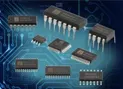
32bit VLN1M series SOP 8/16pins ( built-in flash memory)
body | duration | MIDI | I/O | sampling frequency | power amp | push-pull | built-in flash memory |
VLN1M04S8X
(NX11M22AS8) | ~2min | 16ch | 4 | ~44.1kHz | 1.3W | v | 4Mb |
VLN1M08S16X
(NX11M23AS8) | ~4min | 16ch | 12 | ~44.1kHz | 1.3W | v | 8Mb |
VLN1M32S8X
(NX11M24AS8) | ~16min | 16ch | 4 | ~44.1kHz | 1.3W | v | 32Mb |
VLN1M32S16X
(NX11M25AS8) | ~16min | 16ch | 12 | ~44.1kHz | 1.3W | v | 32Mb |
32-bit MCU with Sub-Band Coding & 16-ch MIDI
The VLN1M(NX11M) series is a 32-bit MCU based high-quality speech/MIDI processor, which is specially designed for customers to innovate with advanced DSP power. It is embedded with OTP (One Time PROM) for mass production, such that no mask is required while MOQ / Lead Time are kept minimized.
Feature
The VLN1M(NX11M) series consists of several derivatives with respect to ROM (OTP), RAM, I/O and functions. With memory-mapped architecture, the VLN1M(NX11M) can address up to 16MB space that includes memory, register files, peripheral and SPI flash storage (including instruction/data modes). SBC (Sub-Band Coding) is achieved with greatly enhanced quality & much less memory size compared against traditional ADPCM coding due to the incorporation of efficient DSP algorithms as well as the upgrade of H/W spec. Via the high performance of 32-bit MCU, the S/W-based MIDI synthesizer can reach more than 16-ch polyphonic channels. All data including SBC / MIDI files, wavetable timbres, XIP codes and general user data, can be accessed from the external SPI flash.
•
Wide Operating Voltage: 2.4V ~ 5.5V.
•
32-bit CPU core.
•
Power management to support 4 operating modes: Normal / Slow / Standby / Halt mode. At Halt mode, the consumption current is less than 1uA.
•
LVD (Low Voltage Detection): Total 6-level options: 3.6V, 3.4V, 3.2V, 2.6V, 2.4V, 2.2V.
•
Timers (Timer0 / Timer1 / Timer2): Each Timer consists of divider and 16-bit down-counter with various clock sources.
•
Two PWM Generators (PWMA / PWMB).
•
Built-in MIC bias, 2-stage of pre-amplifiers and AGC/PGA for gain control.
•
Built-in 14-bit DAC + 1.3-Watt Push-Pull power amplifier.
•
SPI protocol
•
RTC with 4KHz / 1KHz / 64Hz / 2Hz interrupts.
•
Support OTP Security Lock to prevent OTP data from being read.
•
S/W-based Speech/MIDI Codec.
•
Noise filter @ 4x up-sampling.
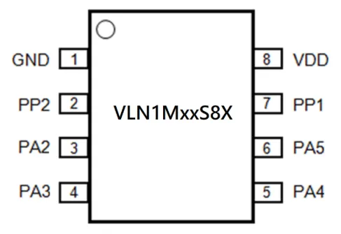
SOP 8pins assignment
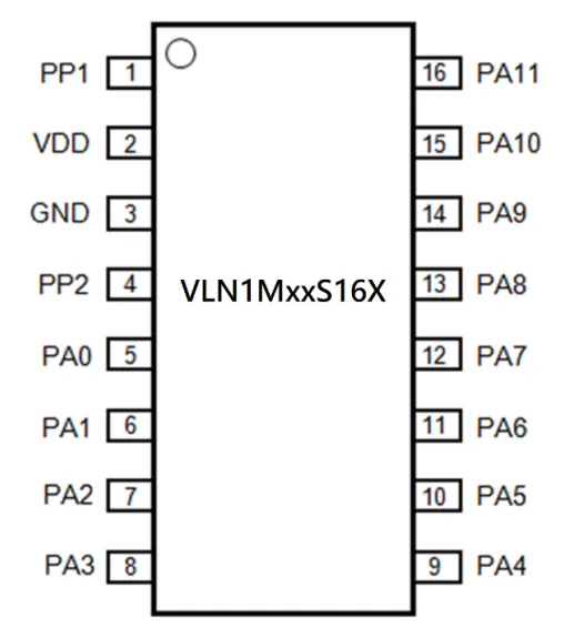
SOP 16pins assignment
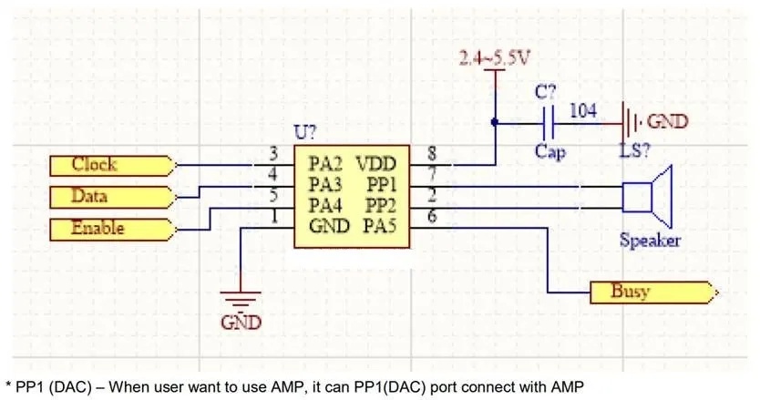
SPI protocol application circuit with MCU
Oscilloscope wave of SPI protocol with MCU
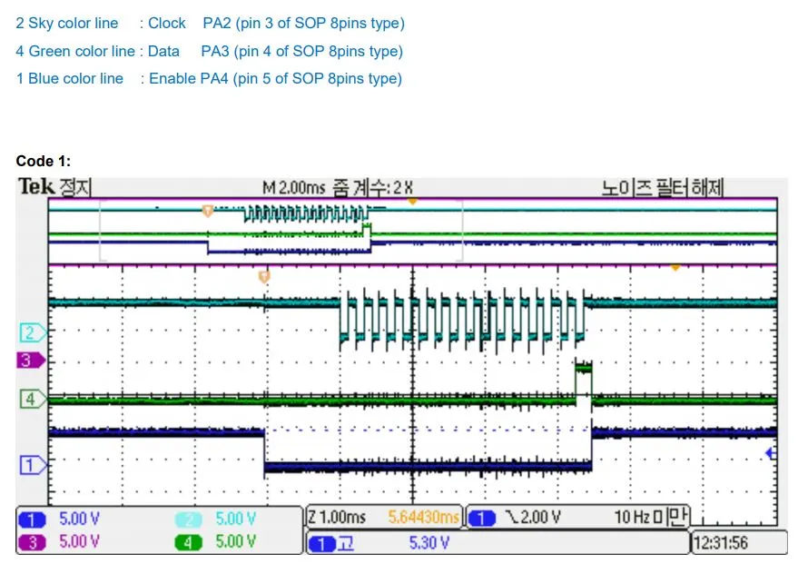
Clock : PA2 ( Enable low 후 900usec 뒤에 clock 시작)
Data : PA3 ( Clock 상승 시 Data값 읽음)
Enable: PA4 ( Enable Low 되면 900usec 후에 Clock 시작)
Busy : PA5 ( 사운드 출력 동안 Low level )
Code 0 : STOP
Code1~1023 : Sound code
Code 1024~1039 : Volume code (Min. ~ Max.)
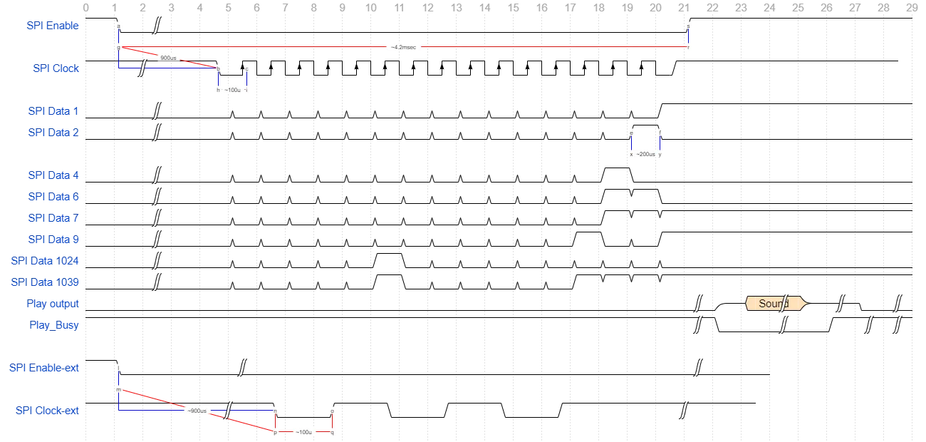
Timing Diagram of SPI protocol with MCU
Clock : PA2 ( Enable low 후 900usec 뒤에 clock 시작)
Data : PA3 ( Clock 상승 시 Data값 읽음)
Enable: PA4 ( Enable Low 되면 900usec 후에 Clock 시작)
Busy : PA5 ( 사운드 출력 동안 Low level )
Code 0 : STOP
Code1~1023 : Sound code
Code 1024~1039 : Volume code (Min. ~ Max.)
VLN1M(NX11M) 3line SPI communication protocol Test video
code: 1 ~ 65535 개 코드 제어 테스트
volume 1 ~ 16 단계 제어 테스트
13201 경기도 성남시 중원구 상대원동 갈마치로 302
성남우림라이온스밸리5차 A-1804호

업체명: (주)시누스 대표자: 김도영 사업자번호:113-81-91015
통신판매업: 2011-경기성남-1834호 개인정보관리자: 김도영
Copyright (C) 2004 SYNOOS Co.,Ltd. All Rights reserved. / Designed by Young Kim